The HUMS is a system made up of three different units that work together to monitor the current status of aircraft/helicopter data. These units include the HUMS AS 10 MPU (Main Processor Unit), the HUMS AS 10 CDU (Control Display Unit), and the HUMS AS 10 DTU (Data Transfer Unit). Together, these units help to ensure the availability, reliability, and safety of aircraft/helicopter engines and important flight data and parameters.
Measured Parameters
Aircraft ID
Pulse data
Analog data
Digital data
Discrete inputs
Data from Air Data Computer
Calculated Parameters
Rotor Torque
Fuel Flow Sum and Fuel Used
Delta NG
VNE
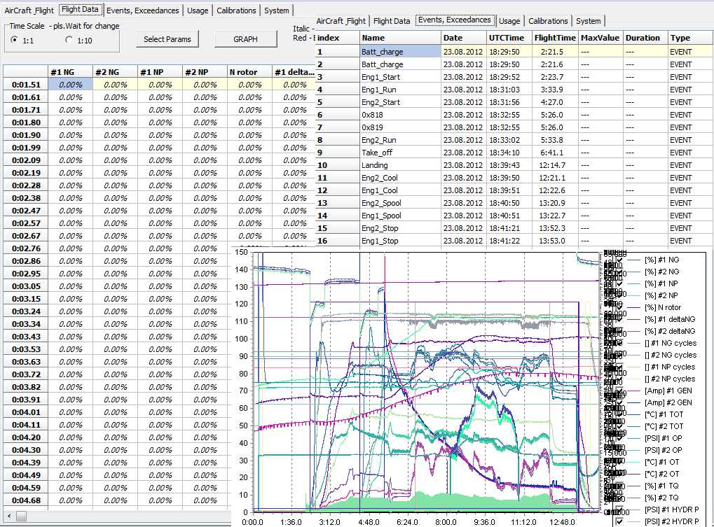
Exceedances
List of Events
Cool and spool Count
Hoist cycles
NG and NP cycles
Flight Log
The system includes a hardware analog/digital converter for both Russian and USA systems, a data collector and storage device, and a data analysis software that evaluates the received and categorized data using a mobile or front-end application.
Measured parameters
Aircraft ID
The Aircraft ID is a unique 7-bit number that allows the MPU (Main Processor Unit) to identify which aircraft or helicopter it is installed in. This identification is checked when the MPU is started, to ensure that the stored calibrations and statistics are valid for the specific aircraft or helicopter. If the ID does not match, the default calibration is loaded and the current flight is not added to the saved statistics. The current aircraft or helicopter ID can be assigned to calibrations and statistics by using the “RESET SYSTEM DEFAULT” option in the service menu.
Pulse data
Pulse data is a type of data that is collected by the HUMS system to monitor the speed of the turbine and rotor. The data is collected by measuring the signal frequency of the tachogenerator, which is a device that generates an electrical signal proportional to the rotation speed of a shaft. The data is stored on a CF card every 96 milliseconds, and the stored value is the average of the last 4 measured values. Additionally, pulse data is also used to receive the current fuel flow of the aircraft/helicopter.
Analog data
The system for collecting and analyzing analog data records the average of the last four samples taken every 24ms on a CF card every 96ms. The system also detects when the parameter value goes above or drops below the set limit, known as an “exceedance.”
Digital data
Digital data is collected from Cargo Hook and Hoist systems and stored on a CF card. The Cargo Hook system sends the weight of the cargo on the hook and the Hoist system sends the length of the unrolled rope in meters. These data are used to monitor the status of the cargo and hoist systems during flight.
Discrete inputs
Discrete inputs are sampled every 6ms and the last 16 samples out of the diameter are stored to the CF card every 96ms.
Data from Air Data Computer
The ADC is connected to both static and dynamic pressure sensors, as well as an ambient temperature sensor. The control panel on the ADC has a fixed Baro potentiometer set to a standard pressure of 29.92 conversion height in Hg. The panel is also configured to measure the Indicated Airspeed (IAS) up to 40 knots. The control panel sends data via the ARINC 429 protocol to the processor, where it is stored every 96 milliseconds.
Calculated parameters
Rotor Torque
Rotor torque is the sum of the torque of the left and the right engine.
Fuel Flow Sum and Fuel Used
Fuel flow sum is the sum of the fuel flow for both engines. Fuel used is the total amount of fuel which was consumed during the flight. If the current fuel quantity is greater than zero, then from the amount consumed.
Delta NG
Delta NG expresses a “performance reserve”. The NG delta value is dependent on the engine speed NG a temperature and air pressure.
VNE
VNE is the limit value for IAS. VNE is dependent on the ambient air temperature OAT (Static air temperatuere) and Altitude (Pressure Altitude).
Exceedances
Termination of the exceedance occurs when the hysteresis limit is exceeded. Start date and time the duration and maximum (minimum) value of the parameter during
the duration of the exceedance are stored and expoerted as the Exceedance List Table.
List of Events
OEI, Engine Start, Engine Cool, Engine Run, Engine Abort, Engine Spool, Engine Stop, Landing, Take off, Battery charge, Bleed heater, Bleed valve,
Power OFF, Recording.
Cool and spool Count
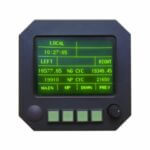
If at least one engine is in the cooling phase, the CDU screen is displayed with by counting down how much time remains until the end of cooling. Cooling time is 30s. If at least one engine is in the spool phase and there is no countdown on the CDU cooling, the spool time is displayed.
Hoist cycles
Hoist cycle is used for counting winch usage. When the winch is rotated, pulses from the Hoist cycle switch are being generated. These pulses are
added to the hoist cycle parameter. At the same time, these pulses are added to the Total Hoist Cycles statistics.
NG and NP cycles
The number of reference cycles consumed between one start and the consecutive shutdown.
Flight Log
If there were any exceedances during power on, then after landing and stopping the engines a the main rotor, Flight log appears on the CDU. In these screens, the exceedance is displayed first that occurred during the flight and are related to the airframe. Then, if so, the exceedance for engines. You cannot view them again when you exit these screens.
HUMS – Data analysis software